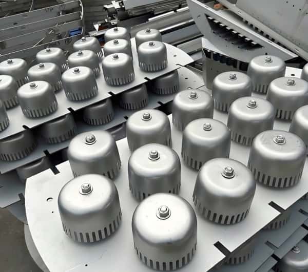
A bubble cap is the component used in chemical columns, especially for enhancing the mass transfer efficiency in gas-liquid contact systems. The earliest bubble cap tray was proposed by Cellier in 1813, but its large-scale application did not occur until the 20th century.The design consists of multiple holes on the tray, each fitted with a short pipe, known as a riser, with a "cap" or bubble cap positioned at the top. These caps are structured to create an annular space with several small slotted openings around them. During operation, liquid flows from the upper tray to the lower tray via downcomers, while gas rises through the risers, dispersing into the liquid layer below the bubble cap. This unique design guides the upward movement of steam and ensures thorough interaction with the liquid, thereby enhancing the mass transfer efficiency while reducing the risk of flooding and weeping.
The bubble cap is a widely used in distillation columns and gas-liquid contact systems. Its application spans industries ranging from petrochemical to pharmaceutical sectors, where it is pivotal to efficient separation processes.
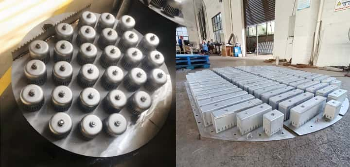
Key Features
1. Durable Material Structure: Our bubble caps are made of high-quality stainless steel, ensuring durability, corrosion resistance, and a long operational life in harsh environments.
2. Optimized Design: Each bubble cap is precision-engineered with optimized slots and risers to maximize gas-liquid interaction. This improves efficiency, reduces energy consumption, and lowers operational costs.
3. Customizability: Bubble caps can be customized to suit specific column sizes and process requirements, including adjustments to diameter and slot configurations to meet unique demands.
4. Easy Maintenance: The modular design allows for easy cleaning, inspection, and replacement of parts, minimizing downtime and enhancing overall production efficiency.
Materials Overview
Our bubble caps are available in the following high-quality materials:
1. Metal Materials: Stainless Steel, Copper, Alloy Steel metal bubble caps.
1.1 Corrosion Resistance: Suitable for acidic and alkaline environments, extending the equipment’s lifespan.
1.2 High Strength: Maintains stable performance under high temperature and pressure conditions.
1.3 Environmentally Friendly: Stainless steel is recyclable and meets modern environmental standards.
2. Plastic Materials: PVDF, PP, CPVC
2.1 Lightweight: Reduces the overall weight of the system, making installation easier.
2.2 Cost-Effective: Lower cost options, suitable for projects with budget constraints.
2.3 Chemical Compatibility: Resists corrosion from various chemicals, ideal for specific process environments.
Types of Bubble Cap Tray Designs
1 Round Bubble Cap Tray
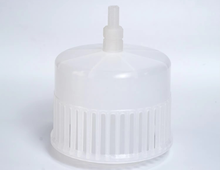
The traditional structure of a round bubble cap tray is shown as below picuture. It consists of an air riser, a bubble cap, and a fixation device. The peripheral edges of the bubble cap are equipped with slits. As the gas flow rises through the air riser and passes through the bubble cap, its direction is altered, and it is dispersed into fine bubbles through the slits into the liquid layer, promoting gas-liquid contact, increasing fluid turbulence, and thereby enhancing mass transfer.

2 S-shaped Bubble Cap Tray
In response to the complexity, high cost, large number of bubble caps per tray, and difficulties in installation and maintenance of the circular bubble cap tray, the S-shaped bubble cap tray was designed in 1950 by Socony Mobil Oil Company, as shown in below Figure
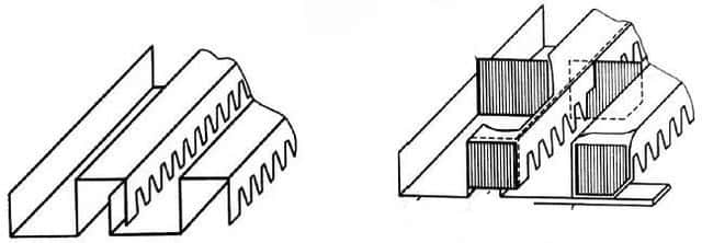
The S-shaped bubble cap tray primarily consists of structurally rigid S-shaped elements that interlink to form bubble caps and air risers. This design simplifies the structure, making it easier to manufacture, install, and maintain compared to the traditional circular bubble cap tray. The air riser area ratio in the S-shaped bubble cap tray is larger than in conventional bubble cap trays, and the effective bubbling area can occupy up to 80% of the tray cross-sectional area. The production capacity of this tray is 10-20% higher than that of a circular bubble cap tray, and its operational flexibility can reach 6-8. The S-shaped bubble cap tray reduces the wasted effective mass transfer space due to the spacing between holes in circular bubble cap trays, utilizing the bubbling space more efficiently. This design improves the tray's flux, reduces its cost, and performs well in applications such as gasoline stabilizing columns, hydrocarbon separation columns, gas absorption towers, crude oil distillation towers, and coking product separation towers, particularly for large columns operating under both normal and high-pressure conditions with high liquid phase loads.
3 Flat Umbrella-shaped Bubble Cap Trays
A major cause of high pressure drop in traditional bubble cap trays is the significant height difference between the upper edge of the air riser and the lower edge of the bubble cap slits. After gas rises through the air riser, it reverses direction and flows downward through the liquid layer, causing a large pressure drop. To address this issue, flat bubble cap trays were introduced. Three structural types of flat bubble cap trays are shown in Figure 4. The air riser in flat bubble cap trays is very short, with its upper edge lower than the lower edge of the bubble cap slits, and the riser is shaped like a horn. This design reduces reverse flow of gas, significantly lowering the pressure drop. Additionally, due to the optimized flow path, the anti-blocking ability is enhanced.

The air riser and the bubble cap edge are vertical in flat bubble cap trays, and the rising gas creates vortices on top of the bubble caps, resulting in relatively high flow resistance. Therefore, further modifications to the air riser holes and bubble cap walls have led to the development of umbrella-shaped bubble cap trays, also known as ACV trays, as shown in Figure 5. In umbrella-shaped bubble cap trays, both the bubble cap and air riser sidewalls are tilted at a 45° angle. This design increases the slit passage area compared to trays with vertical sidewalls, reduces the internal vortex in the bubbles, and improves the flow path, thereby reducing the pressure drop.
4 Strip-Slot Bubble Cap Trays
When using traditional bubble cap trays in large columns, a large number of bubble caps are required per tray, which poses significant challenges for installation and maintenance. To overcome this problem, strip and slot bubble cap trays were designed, inspired by the S-shaped bubble cap tray. The structure of a slot bubble cap tray is shown in Figure 6. The slot bubble cap tray replaces the single circular bubble cap with two types of U-shaped slots of different widths. Wide slots are arranged on the tray, with the horizontal portions forming liquid flow spaces, and the vertical slot walls and adjacent U-shaped slots form air risers. Narrow U-shaped slots cover the air risers, and both ends are sealed to form bubble caps.

Strip and slot bubble cap trays retain the advantages of traditional bubble cap trays while increasing the area of open holes on the tray, reducing pressure drop and cost, and making fabrication and installation more convenient.
5 Bubble Cap Tray with Flow Guide Vanes
A bubble cap tray with flow guide vanes is created by adding guide vanes in the tangential direction to the air risers of flat bubble cap trays, as shown in Figure 7. The gas flow follows the guide vanes and enters the liquid layer. This configuration results in better gas-liquid contact, and the centrifugal force generated by the vanes helps separate entrained liquid droplets, improving tray efficiency and reducing mist entrainment.

6 Rotary Bubble Cap Tray
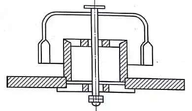
The bubble cap tray with flow guide vanes places the flow guide device on the air riser, while the rotary bubble cap tray has the guide vanes placed on the slits, as shown in Figure 8. The bubble caps can rotate and float up and down, making this tray a hybrid between a bubble cap and a floating valve tray. The rotation of the vanes and their stirring effect break up the gas and liquid layers, significantly enhancing the gas-liquid mass transfer process. The centrifugal force produced by the rotation causes most of the liquid droplets to move in the horizontal direction, reducing mist entrainment. Additionally, the rotation eliminates dead zones on the tray. The bubble caps can rise and fall in response to changes in gas load, increasing the tray's operational flexibility.
Advantages
1. Efficient Gas-Liquid Contact: The large contact area between gas and liquid ensures high tray efficiency.
2. Wide Operating Range: Bubble caps can maintain efficient operation even when load fluctuations occur.
3. High Production Capacity: Suitable for large-scale production operations.
4. Resistance to Clogging: The design minimizes clogging and ensures stable and reliable operation.
Key Design Parameters for Bubble Cap Design
Main Types and Shapes of Bubble Caps:
1. Circular Bubble Caps: Currently the most commonly used in industry due to their simple structure, ease of processing, and maintenance.
2. Strip Bubble Caps: Suitable for specific applications, where the bubble cap spacing can be adjusted to control gas flow distribution and gas-liquid contact efficiency.
Shape of the Slits on the Bubble Cap Walls:
1. Rectangular Slits: Provide uniform gas flow distribution and relatively low resistance.
2. Triangular Slits: Can increase the jetting force of the gas flow, but may increase resistance.
3. Trapezoidal Slits: Combine the features of both rectangular and triangular slits, aiming to balance the jetting force and maintain low resistance.
Structural Design of Bubble Caps and Gas Risers:
1. Bubble Caps with Gas Risers: The bubble cap is equipped with a gas riser, which is fixed on the tray. The gas phase enters the space between the bubble cap and gas riser.
2. Gas Flow through the Bubble Caps: The gas phase is ejected through the slits of the bubble cap at a certain velocity, creating bubbling contact with the liquid on the tray to facilitate mass transfer.
Size Parameters of Bubble Caps:
Common industrial sizes include 50, 80, 100, 150 millimeters, etc.
Other Technical Parameters May Include:
1. Material Selection: The material of the bubble cap tray should be selected based on the chemical medium, temperature, and pressure requirements of the application. Common materials include stainless steel, carbon steel, alloys, etc.
2. Width and Spacing of Slits: The design of slit width and spacing affects gas-liquid mixing efficiency and the pressure drop across the tray.
3. Gas Ejection Velocity: The gas ejection velocity affects the mass transfer efficiency. Excessively high velocity may lead to liquid carryover and bubble cap damage.
4. Pressure Drop: The pressure drop across the bubble cap tray should be within a reasonable range to ensure system energy efficiency.
5. Mass Transfer Efficiency: The mass transfer efficiency of the bubble cap tray is an important performance indicator.
In order to achieve the optimal mass transfer effect, the design of the bubble cap tray typically requires detailed engineering calculations and experimental testing. The performance of the bubble cap tray depends not only on the design of the bubble cap and gas riser but also on factors such as the liquid flow rate on the tray, the tower pressure, and the operating temperature. Therefore, when customizing bubble cap trays, it is essential to collaborate with tray manufacturers or specialized chemical equipment engineers to ensure that the design meets the specific requirements of the application.
Advantages of Using Bubble Caps
1. High Efficiency: Bubble cap promote uniform steam and liquid distribution, ensuring optimal mass transfer and improving overall process results.
2. Versatility: Suitable for various operating conditions, including different temperatures, pressures, and flow ranges.
3. Enhanced Stability: Bubble caps maintain consistent performance even during load fluctuations, making them ideal for critical applications.
4. Energy Savings: The optimized design reduces system pressure drop, contributing to lower energy consumption.
5. Cost-Effectiveness: The long lifespan and low maintenance requirements help reduce overall operational costs.
Bubble Cap vs Other Tray Technologies
| Feature | Bubble Cap | Tray | Float Valve Tray |
|---|---|---|---|
| Efficiency | High | Medium | High |
| Pressure Drop | Medium | Low | Medium |
| Durability | High | Medium | High |
| Cost | Medium | Low | High |
Customization Options
1. Size Adjustment: Adjust diameters and heights to meet specific process needs.
2. Material Selection: Choose from a variety of materials to suit specialized environments.
3. Specialized Design: Customize based on flow rates, pressure, and temperature requirements.
Applications
Bubble caps are critical components in the following processes:
1. Distillation: Enhance separation efficiency based on boiling points.
2. Absorption: Facilitate the capture and removal of gases in liquid media.
3. Desorption: Ensure efficient removal of volatile components.
How to Choose a Bubble Cap Manufacturer
1. Quality and Reliability: Select manufacturers known for high-quality, corrosion-resistant bubble caps for reliable performance.
2. Customization Options: Ensure the manufacturer offers customization based on your distillation requirements.
3. Industry Expertise: Choose a manufacturer with extensive experience and technical knowledge.
4. Excellent Customer Support: A strong support team is crucial for addressing any issues and ensuring smooth operations.
5. Competitive Pricing and Timely Delivery: Compare pricing and delivery times to select a manufacturer offering both value and reliability.
Installation and Maintenance Guidelines
Installation Notes
1. Ensure the inner surfaces of the equipment are clean and free of contaminants.
2. Ensure a tight fit between the bubble cap and the tray to prevent leaks.
3. Avoid overtightening during installation to prevent material damage.
Maintenance Tips
1. Regularly inspect for wear and corrosion.
2. Thoroughly clean during shutdowns to prevent clogging and maintain efficiency.
3. Replace parts promptly to ensure optimal operational performance.
